
Technical project for the in-building telecommunications infrastructure (ICT) of a new residential building, drawn up in coordination with the architectural design.
- 5
- documents: report, drawings, specifications, budget and health and safety
- 16
- drawings and diagrams, one per floor and per network
- Outlet by outlet
- we calculate the signal at every outlet, for every technology
- Coordinated
- with the architectural design from the start
ICT
- Scope
- Seville, for an architecture studio
- The challenge
- Provide a four-storey building with every telecommunications service, in coordination with the architectural design.
- What we did
- Complete ICT project under Royal Decree 346/2011: TV and radio with provision for satellite, telephony, coaxial cable and fibre to every home, with floor-by-floor drawings and network diagrams.
- Result
- 10 user access points (9 homes + 1 shared room) with every service, and a project verified by the COIT, ready for approval.
How we solved it
-
 Enlarge
Drawing 1 of 4
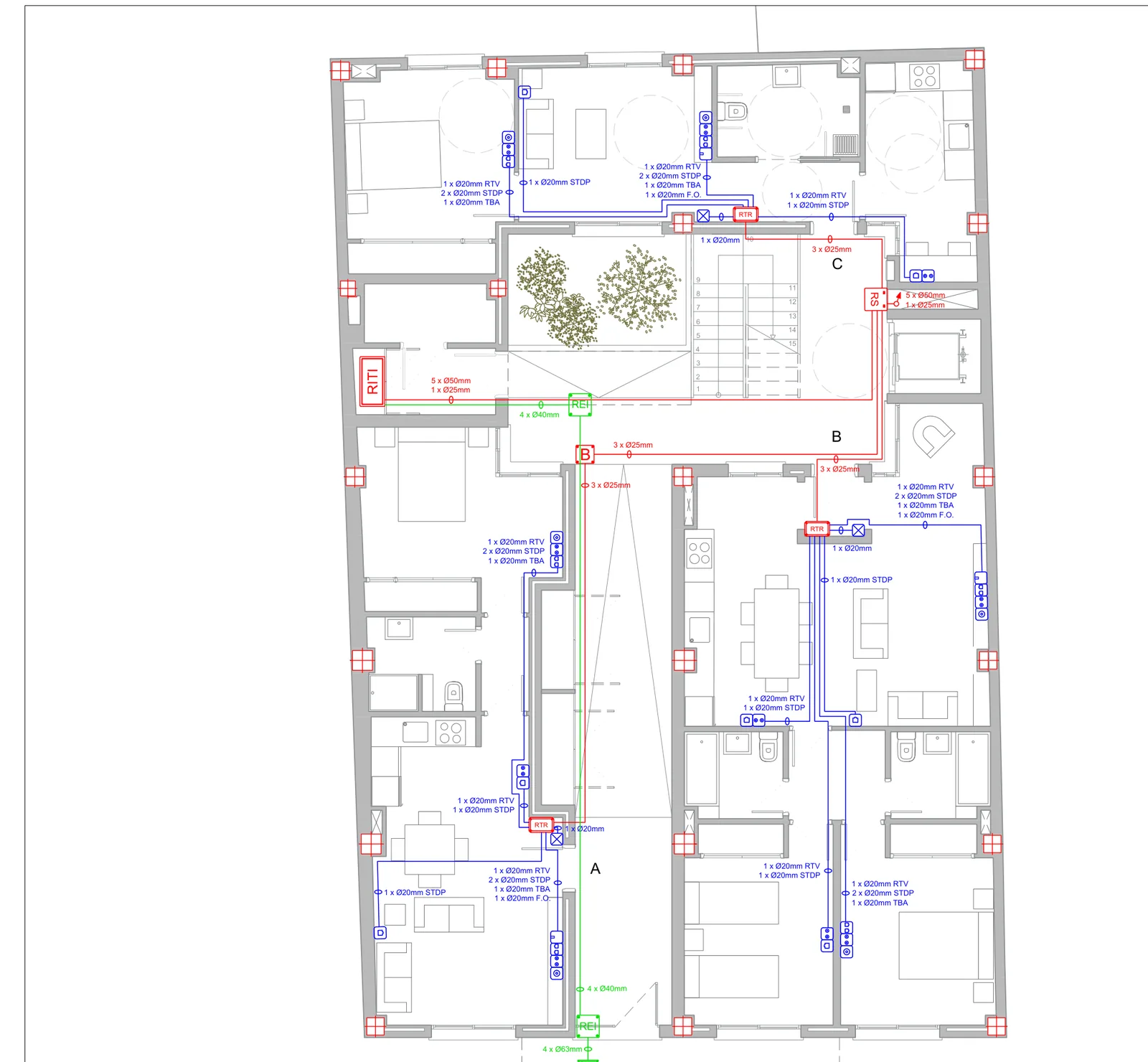
One floor, outlet by outlet
On the architectural plan we draw the route of every conduit, the boxes and the outlets in each room. We do it for every floor and for the roof, where the aerials go.
-
 Enlarge
Drawing 2 of 4
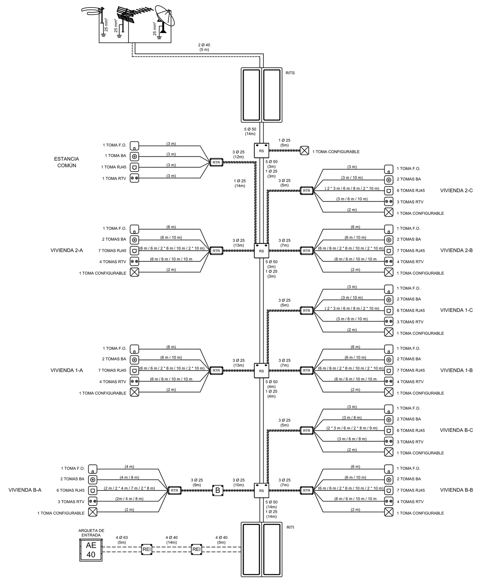
Every network in one diagram
The general diagram brings every network together: from the entry manhole and the aerial to each outlet, through the telecom rooms (RITI and RITS) and the boxes on each floor.
-
 Enlarge
Drawing 3 of 4
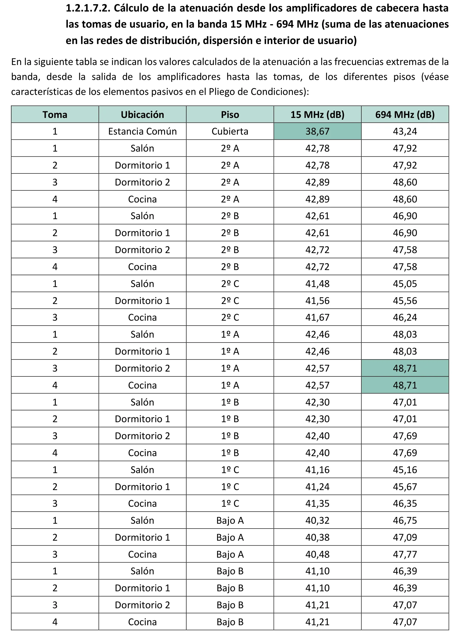
Every outlet, calculated
We calculate the attenuation from the headend to every outlet in every home, at both ends of the band. The worst outlet sets the amplifier levels, guaranteeing 54 dBμV of digital terrestrial TV signal at all of them.
-
 Enlarge
Drawing 4 of 4
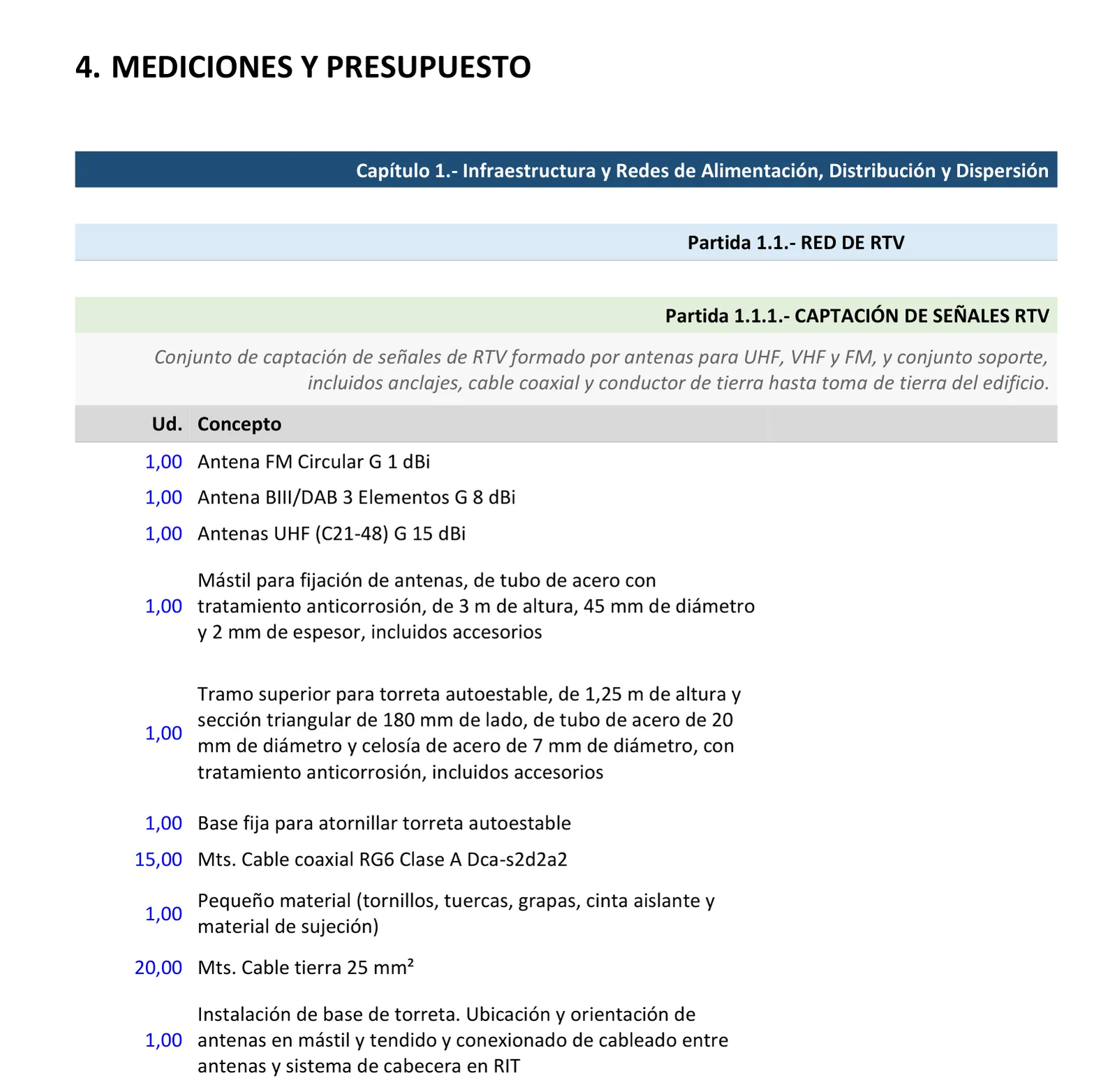
Measured item by item
The bill of quantities and the budget break down every item: what it includes and how many units it needs. That way any installer can quote for exactly the same thing.
Drawings from the real project. We have removed the personal data they contained.